|
Overview :
The
standard ignition modules and coils (not coil pack or electronically controlled
systems) fitted to many small Japanese engines aren't very wonderful. They are
better than points (hell, anything's better than points....) but they are pretty
marginal in terms of energy supplied to the spark plug. So what can be done
easily and cheaply?
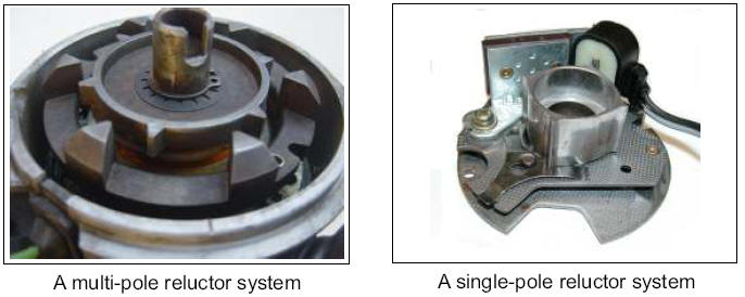
If you have reluctor
style distributor (has a star shaped wheel that generates the timing pulses,
usually mounted right under the rotor button) the answer is surprisingly cheap
and relatively simple.
This upgrade will
work with either type of Variable Reluctance distributor pickups shown below. Hall
Effect systems will not be suitable for this particular modification.
You have
been WARNED!
However before you
race out and start chopping into your pride and joy, read the whole article and
have a careful look at your existing ignition system to ensure its essentially
as described. Due to the DIY nature of this description and variation car to car
there may be some challenges you have to overcome.
The article is a guide - not a guarantee! DTec accepts no responsibility should
you decide to undertake this modification - its entirely at your own risk.
What you need:
Looking at
the technical specifications, the old straight six cylinder Holden has the
highest output module and coil fitted to
readily available production cars. Go to a self serve wrecker, locate a suitable
donor vehicle, and on the distributor base will
be a cast flange with a sheet metal cover, under which will be a Bosch module -
the last three digits should be 021. It will
have four terminals.
Disconnect, unscrew
it and try NOT to wipe the white heatsink paste off the module base - it helps
with heat conduction to the
heatsink.
You will also need
the ignition coil as well as the mounting bracket and HT lead just to be safe.
It's an oil filled unit (the cylinder type) but if you want a more modern
looking, transformer coil then you need a Bosch HEC715 (female HT) or a HEC716
(male HT) They all perform similarly but the HEC715 / 16 won’t be common on
wrecks.
If you want to purchase new components see below for BOSCH part numbers.
Making the
modifications :
Using a
timing light, establish the standard timing at idle. In order to do this you may
need to refer to the manufacturers specifications to establish exactly under
what conditions the timing is determined.
Before you remove the distributor from your car, and very importantly - mark the
position of the rotor to the distributor body and the distributor body relative
to the engine - to make it easy to reinstall. Scribe a line, Texta mark etc -
but this is important - you WILL need it later.
Now for the "technical" stuff - there will be a pickup in the distributor body -
that is on the same plane as the reluctor (the star shaped wheel that rotates) -
with two wires from this to the ignition module.
If the ignition module is internal to the distributor, you need to cut these
wires and extend them with shielded cable (like audio cable - 2 cores and a
woven metal screen around them) to reach wherever your going to mount the new
module. The screen must to be grounded at one end only.
If your going to remove the pickup to make the installation easier, measure the
gap between the reluctor and the pickup coil. Sheets of paper / plastic etc will
work fine although brass feeler gauges are the correct tool.
Make certain you insulate the joins and ends well (heatshrink) and ensure the
new extended lead is clear of the rotating components of the distributor.
When selecting shielded cable, try and use a good quality silicone insulated
product. Its hot and unfriendly under the bonnet so a quality cable is a good
investment. Keep it away from all the hot engine bits and thermally shield if
necessary - fiberglass sleeving is ideal.
If the ignition module is already externally mounted then you may well be able
to use the existing trigger wiring. Check to see that the cable shield is
grounded at one end only - it is important.
The old module can be removed, or left – its your choice. If you removed the old
internal module, the new shielded cable may be able to exit through the existing
cable grommet making for a neat installation.
If you removed the
pickup from the distributor when cutting and extending the wires, then put it
back and set the gap between the reluctor and pickup coil to the same gap as
when it was removed and all should be well (you did measure it like we suggested
didn’t you.....) or if you have a factory service manual the gap will probably
be provided.
Under NO CIRCUMSTANCES should the two parts touch. If you didn’t measure the gap
before removal remember to allow for a little wobble in the shaft due to
mechanical tolerances and wear.
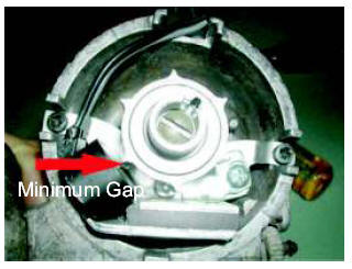
If the gap is too
large the engine will be difficult or impossible to start - too small and damage
will occur.
That's the distributor mods done.
Put the distributor back using the alignment marks – we told you they were
important ! Be careful not to damage the “O” ring or oil seal between the engine
and distributor body.
Mount the coil and
module - a small heatsink is required for the module - so make a 3mm thick
aluminium bracket about 70 x 50mm for the module and that will do. Do not run
the system without a suitable heatsink.
Mounting the module with the coil usually is easiest and in the same position as
the stock coil, as that gives you easy access to the original loom. A new or
recycled plug / socket will make the installation simpler and more professional.
If you wiped of the heatsink paste during removal of the module, electronic
component suppliers usually sell it. It is important to make good thermal
contact between the module and its new heatsink.
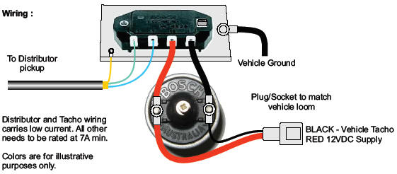
The Wiring :
The
connections on the module are :
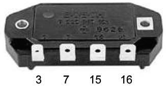
So.... ignition power
goes to the coil positive terminal and to module terminal 15, a ballast resistor
is NOT required. In fact a ballast wire or resistor will undo all your good
work! You can pick up power from the old coil positive connection on the loom
(not the old coil - just its loom connection).
Coil negative goes to module terminal 16, connect the new coils negative to the
old coils negative terminal on the loom so the ECU / tacho gets ignition pulses.
The shielded cable
that you have just installed goes to terminals 3 & 7 - don't make them permanent
just yet. Make sure the screen is grounded at one end as described previously.
Module shell is
connected to the vehicle ground via its bolted connection to the heatsink. Make
certain both the module AND heatsink have a good electrical ground connection.
“Star” or serrated washers may be used to assist.
The BIG
MOMENT :
That's
it... start the monster.
Get a timing light -
if you have to substantially rotate the distributor body to get the timing
right, then reverse the connections to terminals 3 & 7 and recheck.
This matters -
reverse connection might run but the dwell control in the module will operate
incorrectly and the rotor may no longer align with the internal posts / lead
connections molded into the distributor cap,
If you have an
Oscilloscope then you can verify the polarity manually. With the distributor
removed (remember to mark alignment as before) - rotate the distributor drive in
the normal direction of rotation and observe the pickup coils output waveform.
As the pole passes the coils projecting tooth the waveform should swing positive
first then go negative. You have now identified the trigger coils “+” and “-”
wires so connection to the module is straightforward.
Connecting a standard oscilloscope to the coil or module whilst the vehicle is running
is NOT recommended.
You now have a high performance, variable reluctance triggered, inductive
ignition system, powerful enough for most boosted installations let alone a
stock vehicle - more than a match for OE or aftermarket systems.
Total cost second hand - depends on wreckers but $20 is about it. New parts will
obviously cost more.
Do it
PROPERLY :
If your going to do
this - do it properly, nothings worse than poor wiring leading to breakdowns. If
your mystified by all this then DON'T ATTEMPT IT, its not that hard but some
basic electrical and mechanical knowledge is required.
The underlying Bosch module and coil are very reliable, so ensure you
workmanship is to the same standard.
BOSCH Part Numbers :
Number on Ignition
Module : 9222 067 021
Ignition Module as a retail boxed assembly : 9222 067 024 or BIM024
Ignition Coil - cylindrical oil filled : 9 220 061 445 (or other models as
specified for the “021” module)
Ignition Coil - transformer type : HEC015 (Female HT) or HEC016 (Male HT)
All we ask is that if you find the
information interesting then post a link on your site, It will encourage us to
continue publishing! Thanks.
◄ Back to
Tech Articles Page
◄ To Dyno
DIY System Page
|