![]()
Inertia Dyno Design Guide
|
|
|
|
Aim of this DIY article This article has been written to help provide ideas for those building a home made inertia dynamometer. It’s a collection of information and concepts based on our research and lessons learnt from personal ‘trials and tribulations’. Our goal is to save you time, money and most importantly to help you design a safe and rewarding DIY inertia dyno. Most mechanically competent individuals that set out to build an Inertia dyno find that the part they thought would be the most difficult, the inertial mass assembly (flywheel), can easily be made inexpensively. However, they soon realise that the hard part is in the electronics and programming needed to actually get those power figures. DTec’s ‘Dynertia3’ Dyno System & Software eliminates the need for you to worry about complex electronics, physics and programming, you just handle the mechanical design. With a little research and guidance from this article you’ll soon be on your way to owning your own inertia dynamometer. Please check out this website for additional information and tools to help. A dyno that is quick to use, consistent, reliable and inexpensive can be a real profit maker for your business!
What’s a Dynamometer? Basically, a dynamometer (‘Dyno’ or ‘Dyne’ for short) is used to measure the power and torque output of an engine. There are two main types of dynos, ‘engine dynos’ that are coupled to the engine either directly or via gears/chain/belt and than there’s ‘chassis dynos’ that measure power at the wheels, usually by having the vehicle drive on a single roller (common on bike dynos) or between a set of rollers. Both chassis and engine dynos are further separated into two types- · ‘Inertia dynos’ use the engine to simply accelerate an inertial mass (we will call this a ‘flywheel’ for simplicity). If we know the flywheels inertia (resistance of an object to a change in its state of motion) and the rate it accelerated we can calculate the power required to do this. If we can repeatedly measure and calculate the power in small steps we can produce an accurate graph of the engines power characteristics on a PC. · ‘Steady state’ dynos use a device often called a ‘brake’, ‘absorber’ or ‘retarder’ to apply a load to the engine and hold it at a constant speed against the open throttle. The torque is applied to the brakes housing, which is restrained from rotating by an electronic ‘load cell’. The torque is therefore translated to a force that’s read by this sensor. There are many methods of providing the load, both mechanical and electrical. Some common examples of brakes are water, eddy current and hydraulic. Good points of steady state dynos: · The ability to hold at constant rpm whilst you vary the engines load point (control the throttle) is excellent for setting mixtures and timing at individual operating points for mapping programmable engine management units, provided you can keep the operating conditions stable during this time. Bad points of steady state dynos: · Expensive due to the cost of the ‘brake’, load cell and controller hardware. · Complex due to ‘closed loop’ control of the load that’s required to hold engine rpm precisely. · Calibration of the load cell is required to maintain accuracy (a simple enough process using weights). · The braking mechanism of the dyno will generate a lot of heat (engine power is turned into heat) that must be dissipated. Water and hydraulic brakes may even need cooling reservoirs/towers. Engine heat itself must be carefully managed as it may spend considerable time running against the brake under load. · Water and hydraulic units that don’t run load cells (only relevant for very simple designs that base power on flow vs. pressure) must attempt to compensate for the viscosity changes that occur if any sort of decent data is to be obtained. · Even with good computerised control systems the engine may spend long times at each operating point, this can be a concern at high rpm and loads. · ‘Ramp testing’, is where a rapid acceleration rate, without a ‘settling time’, is used in an attempt to produce a power graph quickly and with minimal engine stress. These tests are very sensitive to the acceleration rate used (kph/second, due to uncorrected system inertia); repeatability can also suffer if control electronics ‘closed loop’ system is not ideal. Ramp testing is often performed almost exclusively by some shops. In this case they would be no better off than just having an inertia dyno!
Why build an inertia dyno? Inertia dynos are the cheapest and simplest form of dyno. They really just consist of a flywheel for the engine to accelerate and a sensor to allow a PC to show the results. They are easily constructed and suitable for all size engines, from the tiniest model to the biggest drag car.
The principle is easily adapted to both engine and chassis dyno designs. They can be made fully portable (built into a trailer) as power the supply only needs to run the PC and electronics, not an eddy current brake and large cooling fans. ‘Dynertia’ even gets all its power from the PC’s USB! Also not required is the cooling water supply as needed by water dynos.
Power readings are obtained in a test that usually lasts for less than 10 seconds, that means minimal ‘wear and tear’. It’s no harder on the engine than accelerating down the road and the temperatures are much easier to keep under control (a key to consistency).
Engine conditions are always changing, accelerating and decelerating (unless in a tractor, generator or water pump etc), they are dynamic, they don’t ‘sit still’! Inertia dynos simulate actual conditions just as though you are on the track. Holding an engine in a steady state won’t allow you to test modifications that improve acceleration rate, inertia dynos do, for example the effects of lightening engine and driveline components such as flywheels, cranks, wheels and sprockets shows due to their ability to accelerate faster. These modifications didn’t actually change the engines power, but the real world effects of a quicker bike are revealed.
Dyno Accuracy
Accuracy is not important, repeatability is!
Take your bike to 6 different dynos and you’ll return with 6 different readings. This doesn't matter, what you need is repeatability so that if you put the bike back onto the same dyno the figures are the same. Without this you can’t tune and are wasting your time! Besides being simple (DIY simple) Inertia dynos have nothing that alters, no load sensors to drift etc, that's their secret they are very, very repeatable!
Engine dynos are inherently more repeatable than chassis dynos as tyre contact onto a roller introduces another variable. Tyre temperature, pressure, condition and the downward force onto the roller all play a part but these can be controlled within reason. Convenience of testing is the Chassis dynos strong point.
Inertia dynos give results that reflect the overall performance of the powertrain package as felt on the track. Steady state testing readings are generally higher as they ignore the power that is being consumed in continuously accelerating the engine components e.g. by holding it at separate points to stabilise (called a ‘step test’ on a steady state dyno). The reading may also be a bit high or low based on whether your flywheel inertia vs. the engine power is appropriate, for example a flywheel designed for a road bike will be larger than one designed for a go kart. Repeatability will still be the same!
If your customer only wishes to see 'big numbers' and not necessarily 'better numbers' then he may as well just travel around till he finds a high reading dyno (or the operator fiddles the correction factors) and not bother with tuning!
Operating an Inertia Dyno Setting up: If you wish to record true engine torque (not roller torque) and use engine rpm as the lower scale on your graphs (not kph) then you will need to feed the engine rpm into the measuring system. To avoid needing to connect into the engines ignition system to get rpm, which can be near impossible on many systems, DTec’s Dynertia software just relates the roller rpm to the engine rpm based on what gear your in for the test. To teach the controller the gear ratio (if you wish to do so) you just hold the rpm at a set value in each gear and press the corresponding gear ‘button’, the values are stored for that bike so that any gear used for testing will have the correct rpm and torque data. The current weather conditions- temp, relative humidity and absolute barometric pressure need to be entered into the software so that the data is corrected to a standard set of conditions; this allows consistency in the results as the environmental test conditions change. It is important to keep an eye on your weather station (not very expensive for basic units) whilst running tests, you will be surprised how quickly they change! Making a ‘run’ (or ‘pull’): With the bike or engine safely secured, start the engine and warm up to operating temperature. If the vehicle/engine has a gear box then it is advised (and often overlooked) to run through the gears to ensure the gear box and oil are also up to operating temperature. Run the engine below the speed you wish to start testing at, or on a 2 stroke with a centrifugal clutch raise the rpm to let the clutch lock. Start your data acquisition system recording (F12 on DTec Dynertia system) Accelerate rapidly at wide open throttle until the max rpm you wish to test. Pull in the clutch (if fitted) and simultaneously shut off the throttle. Stop your data acquisition recording (F12 again on DTec Dynertia system), apply the brake to stop the flywheel gradually and shut down the motor. It’s as simple as that! You can now view your data and analyse the results.
Step one in Dyno Construction Read this article fully and then research what others have done and learn from them. We strongly suggest you open ‘Google’ and select the ‘Images’ tab. Search for anything related to inertia dynos (dynamometers, dyne) and dynos in general, some time spent looking at the pro’s and con’s of others designs will be well worth it. Warning !!!!!!!!! Due to the large mass and speed of the flywheel, great care must be taken in its design and construction. Poor design and construction may result in serious personal injury, property damage and even death! It is possible for the centrifugal force alone to burst a solid steel flywheel if it exceeds its tensile strength. Please use some common sense; the flywheel construction should be left to those who have the equipment and experience to do so safely. A protective ‘scatter shield’ guard must be fitted, in all cases, to cover the flywheel mass in case of catastrophic failure. Guards should be designed so that it is still convenient to inspect and service the equipment, this will help ensure that they are always refitted in future. Safe construction and operation lies with the builder and operator. The information provided here is just that, information; it is not a concise guide, plans or recommendations, just suggestions for you to consider further. As there are countless methods, designs and materials that can be used in inertia dyno construction, DTec and its associates can take NO responsibility or accept any form of liability for damages of any form, material or personal, resulting from using this information! This is one of those projects where ‘over engineering’ is the key!
Dyno Frame Frame design will depend on the dyno type you require. After researching what others have done consider your future testing needs and plan for these at the same time. Inertia dynos can be constructed in many configurations depending on their application. Some examples of layouts we’ve seen are given below- Chassis dyno variations: Single roller, multiple rollers, roller is the flywheel mass, separate flywheels on the same axle as the roller. Also the flywheel may be indirectly driven by gears (such as an old differential), chain/sprockets or drive belts. Engine dyno variations: Generally the flywheel is indirectly driven by gears (such as an old differential), chain/sprockets or drive belts. Directly coupling to the engine can be used but be very, very, careful of flywheel speed. Make the frame sturdy to allow for vibration and fabricate a strong ‘scatter shield’ around the flywheel and fit ’catch loops’ around the axle incase of failure. If testing go-kart engines then allow for easy mounting of standard engines and their accessories by replicating the frame layout. Allow for storage and moving, heavy duty castors can be fitted to smaller units. Perhaps consider a removable ‘table’ for chassis dynos, this will help storage or adapting the assembly to be an engine dyno also.
Flywheel Design
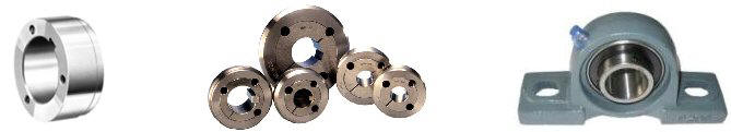
The flywheel design is central to an inertia dyno and is the biggest mechanical hurdle a builder faces. Hopefully the following information will be some ‘food for thought’. Building a flywheel assembly, whether it is for an engine or chassis dyno requires common sense. A ‘safety first’ attitude is needed and you need to know your limitations, admit when a job needs to be ‘farmed out’ to someone with the experience and the equipment to do it right! In the following text the term “flywheel” and “roller” are both the same, they refer to the total inertia assembly regardless of whatever type of dyno (engine or chassis). The term ‘roller’ generally relates to the flywheel mass when it’s used for tire contact as in a chassis dyno. Inertia calculation: The easiest way to work out the mass and moment of inertia for your system is to use the FREE DTec ‘Inertial calculator’ at www.DTec.net.au It will allow estimation of the required inertia before designing your dyno, as well as revealing figures for existing hardware and it doesn’t involve any tricky math’s. If you choose to work out the inertia of a flywheel on your own - To work out the flywheel mass for the moment of inertia figure we calculate the volume of a cylinder and use the fact that one cm³ of steel weighs approximately 7.841717 grams. · The volume of a cylinder = pi * (radius² * thickness) You must treat all your rotating components as individual cylinders and then add them all to get the final inertia value i.e. the axle, flywheel/s, brake rotor, sprocket carriers, mounting flanges or any other rotating component should have its inertia calculated and added together (within reason). · The Inertia J (for a solid uniform cylinder/drum) = mass kg x (radius² m / 2) kg/m² · The Inertia J (for a hollow cylinder/drum) = mass kg x (radius inside² m + radius outside² m / 2) kg/m² How much inertia? Choose a large enough flywheel inertia to give a reasonable acceleration time (around the 10 second mark generally gives good results). If the acceleration rate is too slow then engine temperatures will rise and detonation can occur, this would not normally be a problem if the engine accelerates much faster than this in real use. If the acceleration is too quick then the engines own inertia plays a significant part in the reading and the run wont be very representative of ‘real world’ use either. Choosing an appropriate gear to test in is important to make the most of the inertia without over speeding. If a chain driven engine dyno is being used (go-kart and stationary engines commonly) then there is the option to change sprocket sizes to have the same effect as changing the gear used for testing. If you are testing engines with considerably different power ratings then the flywheel inertia will be a fairly large compromise. It may be worth considering a design that allows easily adding/removing additional flywheels (or engaging them). Inertia mass notes (general): If you double the flywheel radius you will have four times the mass (as it’s squared) and on top of this the actual inertia is this mass multiplied by the radius squared again! If you leave the total mass the same but double the radius (larger, thinner flywheel), you will end up with four times the inertia. So if you wish to use cheaper and slightly thinner plates for flywheels you can achieve good effect still by making a larger diameter (don’t make too big a diameter though). Check what your machine shop can handle before designing large diameter flywheels, you’ll need to work within the limits of their lathe. Don’t overlook the use of multiple smaller flywheels, there’s no rule that says it has to be one single huge chunk of steel. This will also allow you to alter the inertia if required by removing flywheels. The rotating assembly must be perfectly ‘true’ and balanced. Some designers argue about the merits of balancing the assembly and say that it’s not required if machined accurately. We will not enter this debate; it is preferable to have the assembly balanced! Factors such as max rpm, mass, diameter and fixture methods all enter into the decision. Only use solid shafts as your axles, not hollow. Use the largest practical shaft available to suit available pillow bearings, flanges and hubs. It is common practice to weld keyed hubs into the flywheel etc to mount onto the axle; standard hubs are not a precision fit and will ‘cock’ sideways slightly as they have their grub screws tightened, particularly if a single hub is welded to a relatively large flywheel. Always weld a hub each side in this case to provide more location accuracy. The best hubs aren’t just keyed, they are ‘taper locked’ and these provide improved alignment and are easier to re-locate (they don’t ‘seize’ to the shaft).
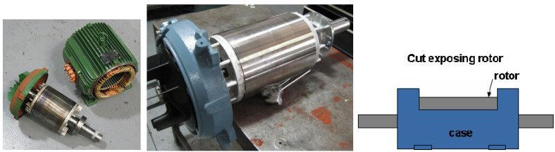
Basic weld on style hub Taper locked weld on hubs Standard pillow bearing Flywheel speeds: A small mass can have the same effect as a large one if it is spun at high speed. Be very careful of this approach! It can be argued that a smaller mass is easier to machine and balance (i.e. can have shaft and mass machined as one piece), however there is a very real chance of catastrophic failure. Other issues are bearing speed limits, these should be checked for all applications (continuous rating differs from peak ratings) and the added complexity (and frictional losses) in any intermediate gearing used. The safest approach is always to design and operate for low rpm of the flywheel. Considering using a larger mass to achieve the same inertia with lower rpm, this may need some form of intermediate gearing (chain or belt) to reduce the flywheels speed in relation to the engine rpm. A large diameter roller on a chassis dyno also has the effect of reducing flywheel speed. Adjust the gear you test in to keep rotational speeds within safe operating limits. As we have no idea of your design, materials, assembly techniques, knowledge and application we cannot advise of any limits. Use common sense and “design and operate for low rpm of the flywheel”. Most well built designs still keep their rpm less than 3000, depending on the flywheel diameter. When designing, work backwards from the maximum expected engine rpm to determine the gearing for a sensible flywheel speed, for chassis dynos use the relationship between tyre and roller circumference (bike kph vs. roller rpm). Flywheel sources: Automotive flywheels come to most peoples mind when planning an inertia dyno. There are several problems: They have very little inertia (and we don’t want to spin them too fast to compensate for this) but most importantly most are not balanced correctly for a dyno, they have a deliberate imbalance to compensate for the balancing of internal engine components i.e. the crank, flywheel and clutch are a balanced assembly. Beware if considering using large machinery flywheels and rail carriage wheels, particularly if second hand, they are often made of cast iron and any unseen defects will be disastrous. They are also generally not designed for high speed operation so would need to be carefully geared/driven. Getting flywheels machined out of solid thick steel is definitely the safe approach but can be fairly expensive, we advise you to shop around carefully and concentrate on machinists who specialize in large jobs. If your testing is for very small engines (model etc) then your choice of flywheel is easier as many objects will have sufficient inertia. You may be able to just use a braking disc or hub as the flywheel. Chassis dyno rollers: For bike chassis dynos you don’t need all the inertia to be in one huge roller (as nearly all are!), you can make a far cheaper roller and add flywheels separately. The roller can be ‘hollow’, weld round ‘end plates’ into the end a large diameter tube. Make the largest practical diameter roller; too small a diameter roller and its speed is too high and tyre deformation becomes an issue, too large and it’s hard to machine. Observe maximum tyre speed ratings also. Rollers should have a deep knurled finish to provide traction or preferable have horizontal grooves machined (straight knurled) across their face for maximum effect. There are traction coatings available for dyno rollers (like course emery paper) but the life expectancy vs. cost may not be worth it. Alternative Flywheel Option The following are untested concepts using old AC induction motors; we can see no reason why it’s not a very practical way to build an excellent cheap inertia dyno. Let us know how you go! Small engine flywheel: Small motor testing only requires a relatively small flywheel. If you can obtain an old AC electric motor with an inductive rotor that has enough mass then you practically have your dyno built. It’s in an easy to mount case (known as the ‘frame’, this can double as the ‘scatter shield’), they have bearings that can be replaced or upgraded easily and electric motors come in all sizes. Even old washing machine motors would possibly suit very small engine testing. As we aren’t using the electrics (though read on) it doesn’t matter if the wiring’s completely burnt out, it just needs decent rotor inertia. Older style motors often had heavier rotors than some of the current ones; you’ll just have to look around at what you can find. Take note of the specification plate as it will have the rpm it’s designed to run at continually, but not the rpm the rotor is safe to, your on your own there! Bike chassis dyno: If you’re lucky enough to score a very large electric motor from an industrial scrap source or motor re-winder (once again, it can be a completely burnt out shell) then it doesn’t take too much imagination to picture what a great roller the rotor would make. If we were to remove the rotor and strip the stator windings from the casing we would then be in a position to cut (grind & oxy cut) a large ‘notch’ in the casing to allow a tyre to contact the rotor when the motor’s re-assembled.
Small Motor Components Medium sized rotor Motor as chassis dyno concept Braking: The following would not be essential as a conventional brake could be fitted but it is an interesting idea. If the stator windings are intact (as in a small engine application using a complete motor assembly), or we replace some coils in the remaining ‘stator slots’ (those not damaged when we cut a hole in the casing) in the above chassis dyno concept we have an interesting possibility. If DC current is switched into the windings on an AC induction motor it creates a very strong braking force. ‘DC injection’ as it is commonly known, is widely used to slow motors down, though it will not brake to zero rpm. So if we wanted to slow the rotor down after a test we could simply switch the stator wires to a DC power source. A variable power supply would need to be used initially to determine the correct current required. Dynertia actually provides a controlled output that could operate a brake function like this! Issues: The main issue with AC motor rotor use would be calculating the inertia of a rotor of unknown density (it’s not a solid mass of the same construction right through); it could involve some trial and error engine testing, though it’s possible to actually test inertia directly also. See the FREE DTec ‘Inertia calculator’ for help.
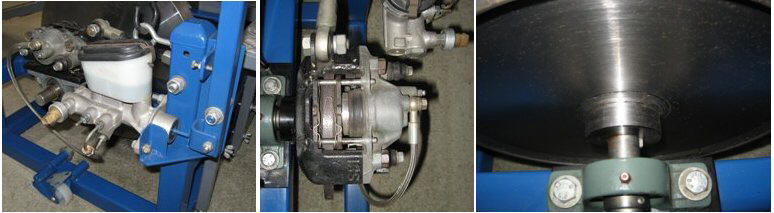
Braking Braking on an inertia dyno is provided for both safety and convenience. In an emergency it is important to be able to stop the mass quickly/safely and during everyday use the brake will avoid unnecessary time wastage while waiting for the mass to gradually stop by itself, this can be a very long time as only frictional losses are occurring (could be 5–10 mins easily, very boring). Having a good brake will also reduce the wear and tear on the vehicles brakes if they are being used also, for example it is common, if motorbike testing, to use the rear brake to assist in slowing the roller. The customer probably came in for dyno testing, they won’t be impressed when the bike’s returned with brake dust everywhere and expensive worn out pads/disc (remember rear bike brakes are quite small as they do minimal effective braking on the road due to weight transferal in comparison to the front brakes). Don’t underestimate the energy required to stop a large spinning mass, remember how long it took the tested engine to accelerate it! The brakes are required to dissipate this stored energy in a fraction of that time if required. Fit brakes from an appropriate source; this will depend on the type of vehicle/engine being tested and therefore your chosen flywheel mass. Under normal dyno use the brake is only used gently and although still dissipating lots of energy it has plenty of time to cool between uses. If an emergency occurs it should still be sized to stop things quickly without causing failure. Avoid applying the brake harder than necessary as it puts massive torsion loads along the shaft, particularly if mounted too far away from the mass (longer, less rigid shaft section to twist); keep the brake disc mounted reasonably close to the mass. It must also be considered that if brake forces suddenly stop the flywheel that the huge stored energy could cause an engine dyno frame to ‘tip’ over as the forces rotate around the axis! When choosing a brake design, consider the mounting requirements and also the method of actuation (convenient lever, cable, pedal etc) and be aware of the calipers or discs need to ‘float’ for self aligning. A pad excessively ‘dragging’ on the disc may result in unacceptable power losses in small engine testing. Motorbike brakes tend to have fully floating discs as well as opposed piston calipers, whilst car brakes will have the movement usually in the caliper (sliding and opposed piston designs etc). If you wish to use the brake to provide an actual load, for example if building up heat, holding down the rpm before a run with an open throttle or using it to load an engine at a particular rpm to tune (not really the normal job of an inertia style dyno) then consider fitting large vented automotive brakes. Automotive brakes: These are very cheap from wreckers, can dissipate large amounts of energy and are readily available with matching discs/master cylinders. The downside is the calipers are often difficult to mount as they are specific to a vehicles mounting design. Have a good look at as many as possible to choose an easy mount style whilst considering availability of replacement pads, discs and spare parts (i.e. choose a common vehicle). An adapter ‘hub’ will need to be machined to fit the disc to the dyno shaft and this must be done accurately as the disc has reasonably large mass and must run true, especially if the caliper is rigidly mounted with little ‘float’ to compensate for disc ‘run out’. A poorly designed/machined assembly will put large stresses on the flywheel shaft and cause vibration issues. 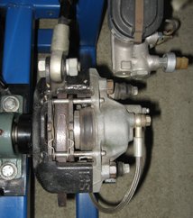
Go-kart brakes: These are generally well suited to small dynos measuring go-karts, stationary engines and small bikes, there are limits to the energy they can dissipate, though some surprisingly powerful packages are available. Discs are easily mounted to most standard shafts with commercial adapters (visit a go-kart store before dyno design to ensure you base your design around an available axle size, use the largest solid size available). Master cylinders, plumbing and mounting hardware are readily available, as are convenient sprocket carriers for use on chain drive engine dynos.
Go-kart brake Motorbike brakes: An adapter ‘hub’ will need to be machined to fit the disc to the dyno shaft and the master cylinder may be hard to adapt for actuating. Rear master cylinders are generally much easier to configure but be careful that it can supply the pressure/volume needed to reasonably operate front calipers if these are used. Go-kart brakes may be an easier option for this size brake requirements.
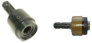
Overrunning Clutch A one-way (or overrunning) clutch allows the engine to come to a stop whilst the flywheel continues to come to a gradual stop. This device is only needed if the engine or vehicle does not have a clutch to disconnect its drive force from the flywheel. After the flywheel has been accelerated and the engine throttle is closed the flywheel will continue to turn, the engine is forced to act as a brake (this is where a clutch would be used if one is available to effectively separate the engine from the flywheel). Excessive engine braking is very hard on an engine due to internal stresses and a critical issue is that 2 strokes get their lubrication inducted with their fuel/air mixture; this is not present or at very least minimal under closed throttle conditions. It is not enough to rely on the flywheel braking fast enough (read “braking” section for the dangers of this) and centrifugal clutches fitted to some applications won’t function when the output is doing the driving, they are designed for the engine to be applying the torque. Whilst we are discussing clutches, a one–way clutch does not negate the need to decouple the engine for starting; this is no problem on motorbikes etc. with conventional clutches. Trying to start an engine whilst it is driving the flywheel is difficult unless it has very low inertia (so therefore probably unsuitable for using anyway), the centrifugal clutch fitted to the engine (assuming it has one) should remain in place to allow starting and warm up but it should be adjusted to ‘lockup’ at low enough rpm to allow testing across the whole useful RPM range. Bearing supply companies have many overrunning drive options (also known as a ‘cam clutches’ in industrial applications) but prices can be ridiculous, particularly for assemblies that are ‘bolt on’ options. If you are prepared to be inventive then basic ‘cam clutch’ bearings are available, but you will need to design a housing to adapt to the dyno application. An approach widely used is the fitment of a modified PTO (Power Take Off) over-running clutch from farm equipment suppliers; they are extremely heavy duty and are fitted to farm implements such as ‘mowers’ that are driven from the tractor directly, these implements have enough inertia to cause some tractors to drive forward if they suddenly slowed down (the blade will continue to turn). The units will typically need machining to remove the internal splines to take your shaft in one side (female) and have the male sectioned machined down to fit inside your other shaft (male). The difficulty in mounting is offset by the cost, they can be found easily for less than AU$400 (we’ve seen them <$150!)
PTO overrunning clutches Do not use automotive starter motor drive pinions as overrunning clutches on small dynos, they will fail! They are designed to operation for short durations (seconds) in normal use and they quickly overheat and seize. A more robust option may be to adapt one of the one-way pulleys from an automotive alternator; these are often used now on passenger sized diesel applications (and some petrol) to decouple drive forces for bearing life, less belt whip, less loading and inertial energy recovery. An alternative option we have seen is a small custom ‘dog clutch’ designed to disengage the motor at the end of a test. It can be fairly simple design just sliding on the shaft as it sees only intermittent use.
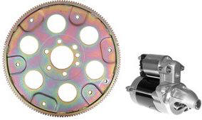
Starting System If the tested engines have no self contained starter then you will need to consider adding one to your dyno. An easy option is to source a matching automotive starter motor and ring gear from the wreckers. Manual vehicles usually have the ring gear pressed (‘shrunk’ fitted really) to their flywheel but automatics generally have it attached to a ‘flex plate’, a thin steel disc that is perfect for mounting via an adapter to the shaft.
Automotive flex plate and starter
Dyno Inertial Physics Dynertia takes care of all the calculations and information processing so you don’t need to panic (or even read this topic)! The understanding of the underlying physics is only an issue if you plan on making your own computerized system for your dyno (or are just very inquisitive). Don’t let us scare you off from building your own system if you have the skills, time and money, I’m just pre-warning you not to underestimate the hardware/software development time and the final total expense of making your own full featured system. Please check out DTec’s ‘Dynertia’ package first to see if it fulfils your needs. We need to measure the flywheel rpm and derive the time between samples with extremely accuracy; this is a job for a dedicated microprocessor based timing system that passes the information onto the PC for processing. There are two main types of sensors commonly used to sense rotation, Hall effect and inductive (variable reluctance). Accuracy of the ‘trigger wheel’ (toothed wheel, vanes or indentations) is of the utmost importance in these systems, the slightest variation results in ‘jitter’ in the output signal. Dynertia uses a different concept; there is no need to use precision trigger wheels and expensive sensors, it time’s rotation to within 1μs (1 millionth of a second) using an optical principle (reflective) that detects a simple adhesive marker on the flywheel. Basic concept: · Calculate the flywheels moment of inertia value, based on its mass and diameter. Store this value as a constant. · Sample the flywheel speed at a certain time interval to obtain the rpm at 2 points and calculate angular velocity at each of these points. · Calculate the energy of rotation for each of these angular velocity’s using the flywheels moment of inertia and then the change (Delta) in energy of rotation between these 2 points. · Calculate the power by dividing the change in energy by the time the change occurred over (time between samples). Calculate torque from this power using engine rpm (based on average engine rpm that occurred between the 2 flywheel rpm points being used). · Repeat and record this data to a PC at high speed over and over, store the results, perform the physics, mathematically smooth the data, apply atmospheric correction factors and graph the results for analysis. Detailed physics calculations: · Inertia J = mass kg x (radius² m / 2) kg/m² (solid cylinder) · Inertia J = mass kg x (radius inside² m + radius outside² m / 2) kg/m² (for a hollow cylinder) · Angular velocity w = (rpm / 60) x 2 x pi rads/sec · Erot = inertia x (w² / 2) Joules · Delta Erot = (inertia x (second w² / 2)) – (inertia x (first w² / 2)) Joules · Power kW = Delta Erot / time for that velocity change in sec / 1000 · Torque Nm = (Power Kw x 9549.305) / engine rpm · Power in HP = Kw * 1.3410 & Torque in ft/lbs = Nm * 0.7376 Atmospheric corrections: · Saturation pressure = 6.11* (10 ^ ((7.5 * Temp / (237.7 + Temp))) · Vapor pressure = Saturation pressure * RH% / 100 (pressure exerted by water vapor molecules) · Pdry = Pabs – Vapor pressure · DIN 70020, corrected to 20ºC & 1013mBar: K = (1013/Pabs) x ((Temp+273) / 293) ^ 0.5 · SAE J1349, corrected to 25ºC, 990mBar: K = ((990/Pdry) x ((Temp+273) / 298) ^ 0.5 x 1.18) - 0.18
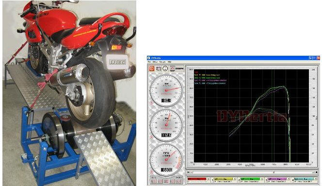
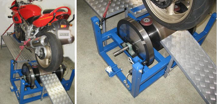
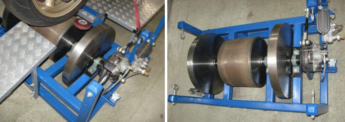
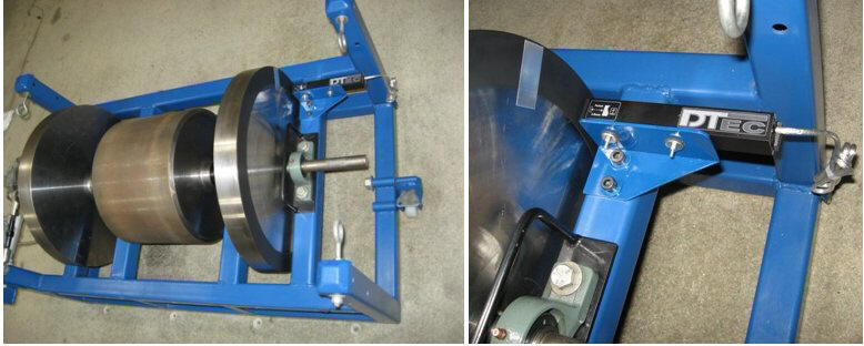
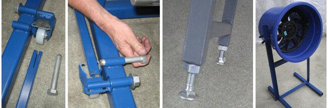
Example of an Inertia Dynamometer Design
The following motorcycle chassis dyno was developed in early 2002, it was designed to test out both dyno design and tuning concepts we had. It has given reliable service ever since. We’ll take a look at it and point out some shortfalls that we can all learn from. NOTE: the flywheel cover guard is not fitted in any photos; this was to allow you to see the components. Never actually run your dyno without one!
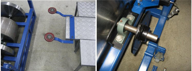
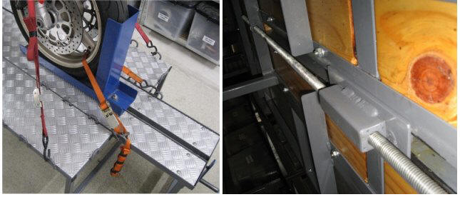
This designs good points: Outside flywheels (the roller is only part of the flywheel mass) can be easily added or removed to alter inertia if required. The roller is a ‘hollow’ design and therefore inexpensive. Plates are welded into the ends of a large diameter pipe and the deep ‘straight knurled’ finish provides unbelievable tyre grip. Small roller blade wheels on the roller sides provide safety incase the bike is not mounted correctly and shifts around. The table and ramp can be unbolted (6 bolts with wing nuts) for storage and an alternative frame to hold an engine can be bolted in its place to make it into an engine dyno. A sprocket carrier can be seen on the axle in some photos for this engine dyno use also. Table has adjustable feet made from cheap bolts (cheap). The brake caliper mount is adapted to a pillow bearing on the axle. This allows self aligning with the disc as the bearing can move in its housing (most pillow bearings have this spherical shell also). This mounting system could easily be replaced with a simple bracket welded to the frame; this may be simpler and removes the need for the ‘torque arm’ (link from caliper to frame) that stops the brake from rotating. The system used, does however, allow the complete caliper/disc assembly to slide off the axle and be fitted to the other side or be easily relocated anywhere on the shaft if your design needs this flexibility. The brake works well and is capable of being used to hold the engine at a particular rpm for brief periods if required (not really the normal job of an inertia style dyno). The lever on the brake cylinder is very easy to operate whilst sitting on the bike but could be a little longer for easier reach. The frame is sturdy, simple and allows for tie down points (eye bolts); it has wheels to allow storage, they fold up to allow flat seating on the rubber pads bonded to the frame base. To move the dyno around we apply a special pole, push the wheels down and slide in a retaining pin. The whole dyno is a compact design. ‘Catch hoops’, metal hoops seen next to roller, surround the axle to dissipate energy (shaft will run around and rub inside hoops) if there is a failure. Guard (not shown in photos) covers all rotating parts and ensures safe operating. Adjusting for the bikes wheel base is easy with the wind in front wheel brace. A simple bolt ensures it’s locked down tight. A cooling fan, made from a modified automotive radiator fan mounted into a large plastic bucket/pot, directs plenty of air over the bikes radiator and engine. Fan runs from a 12V battery. Chosen Inertia allows a test gear to be used that gives good results without over speeding the mass. This designs bad points: The main shaft is too small a diameter for complete safety considering the size bikes tested and the flywheels inertia. ‘catch hoops’ could be stronger design also. Standard weld in hubs are fitted to the roller, flywheels and brake disc. Taper lock ones would have been better as they have induced a slight ‘run-out’. Larger diameter roller would help reduce its rpm when testing in high gears. The original table was made too narrow as storage was a priority. The rider had no where to place his feet and this was soon widened by extending the sides (you can see it looks like 3 pieces). Table design is now too complex due to additions. The front wheel brace needs a wind in side clamp to provide secure sideways support to the wheel. This may make tying the front down easier or unnecessary (providing a brace was behind the wheel also). The
cooling fan could be taller to clear bikes front wheel guard without needing to
raise it.
Inertia Dyno Testing Tips Despite weather correction factors, the best technique is to try and have consistent test conditions in the first place. Ensure good temperature control and airflow at the very least, having an engine breathing back in its own hot and dirty exhaust fumes won’t do anything helpful! Often overlooked is the effect of tyre inflation on chassis dynos, under inflation causes deformation and wastes energy so keep consistent pressures (DTec Dynertia stores any data, records and notes along with the ‘run’ file so you can view for future reference) Don’t limit your testing to full throttle. A simple throttle stop can be adapted to limit the throttle to different settings. At light throttle settings (less engine power) the flywheels inertia has much more effect and this allows very long ‘runs’ to adjust tuning. Let’s face it, how often are you really at wide open throttle? A throttle stop can be a simple piece of curved aluminum that is temporarily attached to the throttle grip with ‘hose clamps’, it is limited when it hits the handle bar controls or master cylinder. This allows you to do runs at fixed throttle settings (e.g. every 20% step till 100% reached) by doing this you can basically record a map of the whole fuelling range. It also allows you to do runs at different ignition angles and throttle openings to confirm settings. It doesn't matter what sort of dyno you use, light throttle fueling adjustments get more difficult with the low power outputs. Generally 'snatchy' operation occurs and lots of the speed points are not obtainable. Even car companies with their huge investments in development programs still do fine tuning on the test track, a climate conditioned chamber with a ‘motoring dyno’ such as AVL’s A/C type is a million dollar investment. When you first crack open the throttle for a run remember that the first couple of seconds may be acceleration enrichment and stabilizing (depending on fuel ECU/carburetor) so allow for this or you will tend to calibrate too rich down the low rpm. The opposite happens when tuning on a steady state dyno, if you ignore acceleration enrichment it’s too lean on the road under acceleration! Final fuelling should be confirmed on the track as should be done with any tuning method. Ignition timing adjustments can be made by overlaying repeated runs with altered timing and picking the timing at any point that gives maximum torque.
Summary Please feel free to comment on the above, we appreciate all feedback and would be very interested to hear about your projects and perhaps we can include some pictures in a ‘photo gallery’ page. Inertia Dynamometers are fundamentally very basic in design, they are a tuning tool that give repeatable and reliable results every time with no need to even calibrate. Regardless of the size engines your tuning and whether for fun or profit, its very hard to go past an inexpensive inertia dyno. DTec’s inexpensive and easy to operate Dynertia package takes care of the complex electronics and software in one go, leaving you free to get on with building and using your very own dyno! Good Luck!
All we ask is that if you find the information interesting then post a link on your site, It will encourage us to continue publishing! Thanks.
|
|
Send mail to DTecDevices@outlook.com with questions or comments about this web site. |